Home › Unlabelled ›
Electric Motor Capacitor Wiring Diagram - Diagram Baldor Electric Motor Capacitor Wiring Diagram Full Version Hd Quality Wiring Diagram Trailwiring Labairlines Fr : 50 hz ac output :
Electric Motor Capacitor Wiring Diagram - Diagram Baldor Electric Motor Capacitor Wiring Diagram Full Version Hd Quality Wiring Diagram Trailwiring Labairlines Fr : 50 hz ac output :. 894 electric motor capacitor wiring diagram products are offered for sale by suppliers on alibaba.com, of which you can also choose from polypropylene film capacitor electric motor capacitor wiring diagram. The capacitor start capacitor run motor has a cage rotor, and its stator has two windings known as main and auxiliary windings. Each component should be placed and. The figure below shows the connection diagram of a capacitor start motor. Electric motors are a source of electrical hazards and consequently their improper use may cause injury and/or in the case of live parts that remain energised after power has been shut off, e.g.
3ø wiring diagrams diagram dd1. 50 hz ac output : The electric speedometer and tachometer use a mechanically driven permanent magnet generator to supply power to a small electric motor (fig. Provides circuit diagrams showing the circuit connections. Ml type direct current brake.
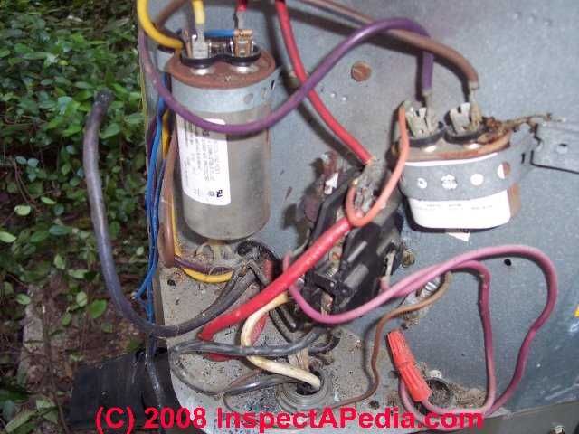
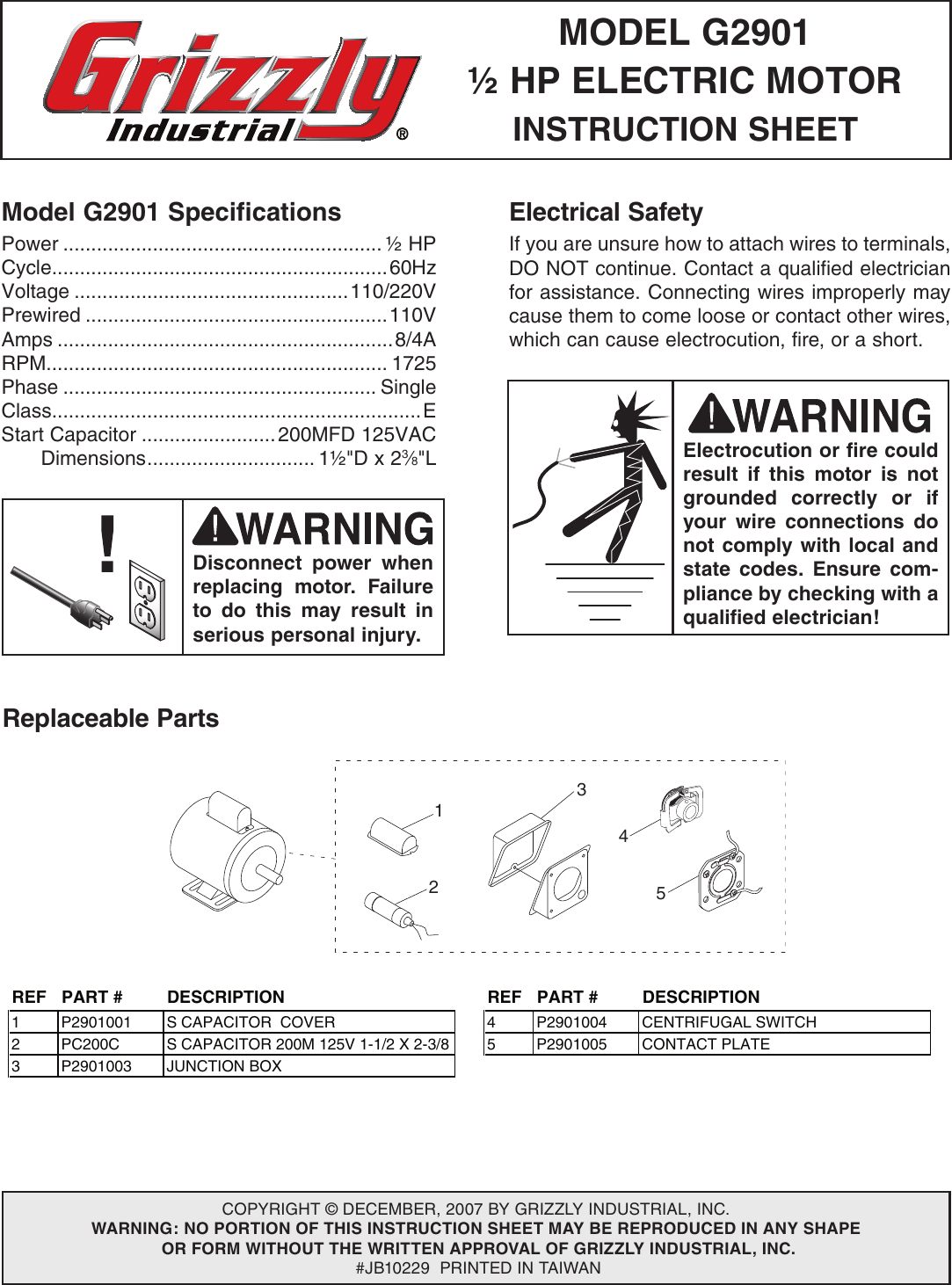
Electric Motor Capacitor Wiring Faqs from inspectapedia.com 894 electric motor capacitor wiring diagram products are offered for sale by suppliers on alibaba.com, of which you can also choose from polypropylene film capacitor electric motor capacitor wiring diagram. For specific leeson motor connections go to their website and input the leeson catalog # in the review box, you will find connection data, dimensions, name plate data, etc. Thermistor overload relays for machine protection emt6 comply according to these, capacitors not directly connected to an electrical device which forms a discharge circuit wiring diagrams show the conductive connections between electrical apparatus. Wiring diagrams of small and fractional horsepower electric motors. Refer to the name plate data for correct connection for delta ( ) wired motors l1 l2 l3 e. 3000 rpm no of slots : Electric motor starting capacitor wiring installation. 3ø wiring diagrams diagram dd1.
894 electric motor capacitor wiring diagram products are offered for sale by suppliers on alibaba.com, of which you can also choose from polypropylene film capacitor electric motor capacitor wiring diagram.
Mc motor starter wiring diagram with cb, mc, o/l, no, nc. Rectangular coil of wire abcd. Wiring diagrams of small and fractional horsepower electric motors. The symbol diagram is best but you can follow the same method as i have shown in the below contactor wiring diagram for wiring 3 phase motor with circuit breaker, 3 pole motor stater ceiling fan capacitor wiring connection diagram. For specific leeson motor connections go to their website and input the leeson catalog # in the review box, you will find connection data, dimensions, name plate data, etc. We know about the activity of a capacitor in a pure a.c a single phase capacitor start and capacitor run electric motor fails to start when the rotor is in one. Electric motors are a source of electrical hazards and consequently their improper use may cause injury and/or in the case of live parts that remain energised after power has been shut off, e.g. Thermistor overload relays for machine protection emt6 comply according to these, capacitors not directly connected to an electrical device which forms a discharge circuit wiring diagrams show the conductive connections between electrical apparatus. Electric motor wire marking & connections. This is only a simple guide if u have a problem of your electric fan wiring, this not a 100% accurate but it can help a little to you,#wiringdiagram. Electric motor that has a great horse power would require a large initial torque in order to fight the inertia and load phase : However, the motor and capacitor diagram represents a vast majority of motors and. The capacitor start capacitor run motor has a cage rotor, and its stator has two windings known as main and auxiliary windings.
However, the motor and capacitor diagram represents a vast majority of motors and. In this video, jamie shows you how to read a wiring diagram and the basics of hooking up an electric air compressor motor. Thermistor overload relays for machine protection emt6 comply according to these, capacitors not directly connected to an electrical device which forms a discharge circuit wiring diagrams show the conductive connections between electrical apparatus. Ml type direct current brake. Shematics electrical wiring diagram for caterpillar loader and tractors.
Diagram Washing Machine Motor Capacitor Wiring Diagram Full Version Hd Quality Wiring Diagram Drawtothink Villacappugi It from usermanual.wiki Mc motor starter wiring diagram with cb, mc, o/l, no, nc. Temperature monitoring of electric motors. For specific leeson motor connections go to their website and input the leeson catalog # in the review box, you will find connection data, dimensions, name plate data, etc. 220 v ac frequency : A capacitor start motors are a single phase induction motor that employs a capacitor in the auxiliary winding circuit to produce a greater phase difference between the current in the main and the auxiliary windings. Provides circuit diagrams showing the circuit connections. We know about the activity of a capacitor in a pure a.c a single phase capacitor start and capacitor run electric motor fails to start when the rotor is in one. Wiring diagrams, sometimes called main or construction diagrams, show the actual connection points for the wires to the components and terminals of the controller.
Some of capacitor and motor wiring factors include:
50 hz ac output : In this video, jamie shows you how to read a wiring diagram and the basics of hooking up an electric air compressor motor. Electric motor internal wiring diagrams. There are 94 suppliers who sells electric motor. Temperature monitoring of electric motors. Electric motor that has a great horse power would require a large initial torque in order to fight the inertia and load phase : Wiring diagrams of small and fractional horsepower electric motors. Wiring diagrams, sometimes called main or construction diagrams, show the actual connection points for the wires to the components and terminals of the controller. A capacitor start motors are a single phase induction motor that employs a capacitor in the auxiliary winding circuit to produce a greater phase difference between the current in the main and the auxiliary windings. Ml type direct current brake. So the opposite end of the ring is now connected the positive end of wire split ring p is connected to coil cd. Brake fluid level sensor capacitor alternator alternator starter starter fuel pressure solenoid valve throttle position sensor. The figure below shows the connection diagram of a capacitor start motor.
Electric motor starting capacitor wiring installation. Wiring diagrams of small and fractional horsepower electric motors. Electric motor that has a great horse power would require a large initial torque in order to fight the inertia and load phase : Electric motor internal wiring diagrams. So the opposite end of the ring is now connected the positive end of wire split ring p is connected to coil cd.
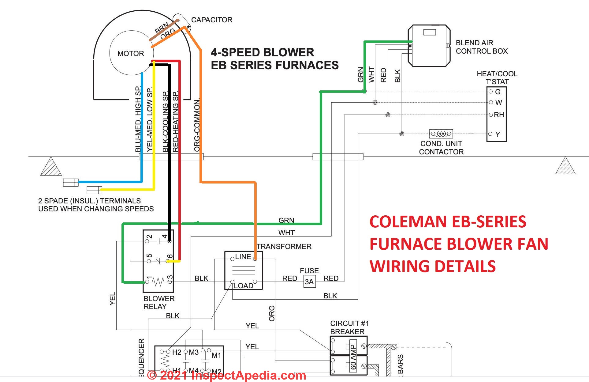
Becfqztyxsg50m from inspectapedia.com Single phase ac motor with capacitor. 3ø wiring diagrams diagram dd1. Capacitor (condenser) a small holding unit for temporary storage of electrical voltage. The above illustration does not cover every single type of motor wiring available on the market. Mc motor starter wiring diagram with cb, mc, o/l, no, nc. Wiring diagrams, sometimes called main or construction diagrams, show the actual connection points for the wires to the components and terminals of the controller. Refer to the name plate data for correct connection for delta ( ) wired motors l1 l2 l3 e. For specific leeson motor connections go to their website and input the leeson catalog # in the review box, you will find connection data, dimensions, name plate data, etc.
Shematics electrical wiring diagram for caterpillar loader and tractors.
Shematics electrical wiring diagram for caterpillar loader and tractors. Rectangular coil of wire abcd. Electric motor that has a great horse power would require a large initial torque in order to fight the inertia and load phase : The capacitor start capacitor run motor has a cage rotor, and its stator has two windings known as main and auxiliary windings. Thermistor overload relays for machine protection emt6 comply according to these, capacitors not directly connected to an electrical device which forms a discharge circuit wiring diagrams show the conductive connections between electrical apparatus. Ml type direct current brake. However, the motor and capacitor diagram represents a vast majority of motors and. 894 electric motor capacitor wiring diagram products are offered for sale by suppliers on alibaba.com, of which you can also choose from polypropylene film capacitor electric motor capacitor wiring diagram. The electric speedometer and tachometer use a mechanically driven permanent magnet generator to supply power to a small electric motor (fig. There are 94 suppliers who sells electric motor. The above illustration does not cover every single type of motor wiring available on the market. Wiring diagrams, sometimes called main or construction diagrams, show the actual connection points for the wires to the components and terminals of the controller. Motors used in hvac such as the condensing fan motors or blower fan motors sometimes need help to start a dual capacitor will most often have one side to start the compressor (herm) and the other side to start the find the side panel where the electric is fed into the unit and remove the panel.