Home › Unlabelled ›
Npn Circuit Diagram : Working of Transistor as a Switch | Electronic circuit ... - These electrical and electronics circuit symbols are used in circuit diagrams to explain how a circuit is note:
Npn Circuit Diagram : Working of Transistor as a Switch | Electronic circuit ... - These electrical and electronics circuit symbols are used in circuit diagrams to explain how a circuit is note:. Circuit or schematic diagrams consist of symbols representing physical components and lines representing wires or electrical conductors. Diagram 'a' shows an npn transistor which is often used as a type of switch. This ldr circuit diagram shows how you can make a light detector. All circuit symbols are in standard format and they are mostly used to draw a circuit diagram and are standardized internationally by the ieee. Pay close attention to see how.
In order to learn how to read a circuit diagram, it is. 2020 popular 1 trends in home improvement, tools, electronic components & supplies, cellphones & telecommunications with circuit diagram of and 1. The diagram shows the two current paths through a transistor. A circuit diagram is a graphical representation of an electrical circuit. This svg diagram uses embedded text that can be easily translated using a text editor.
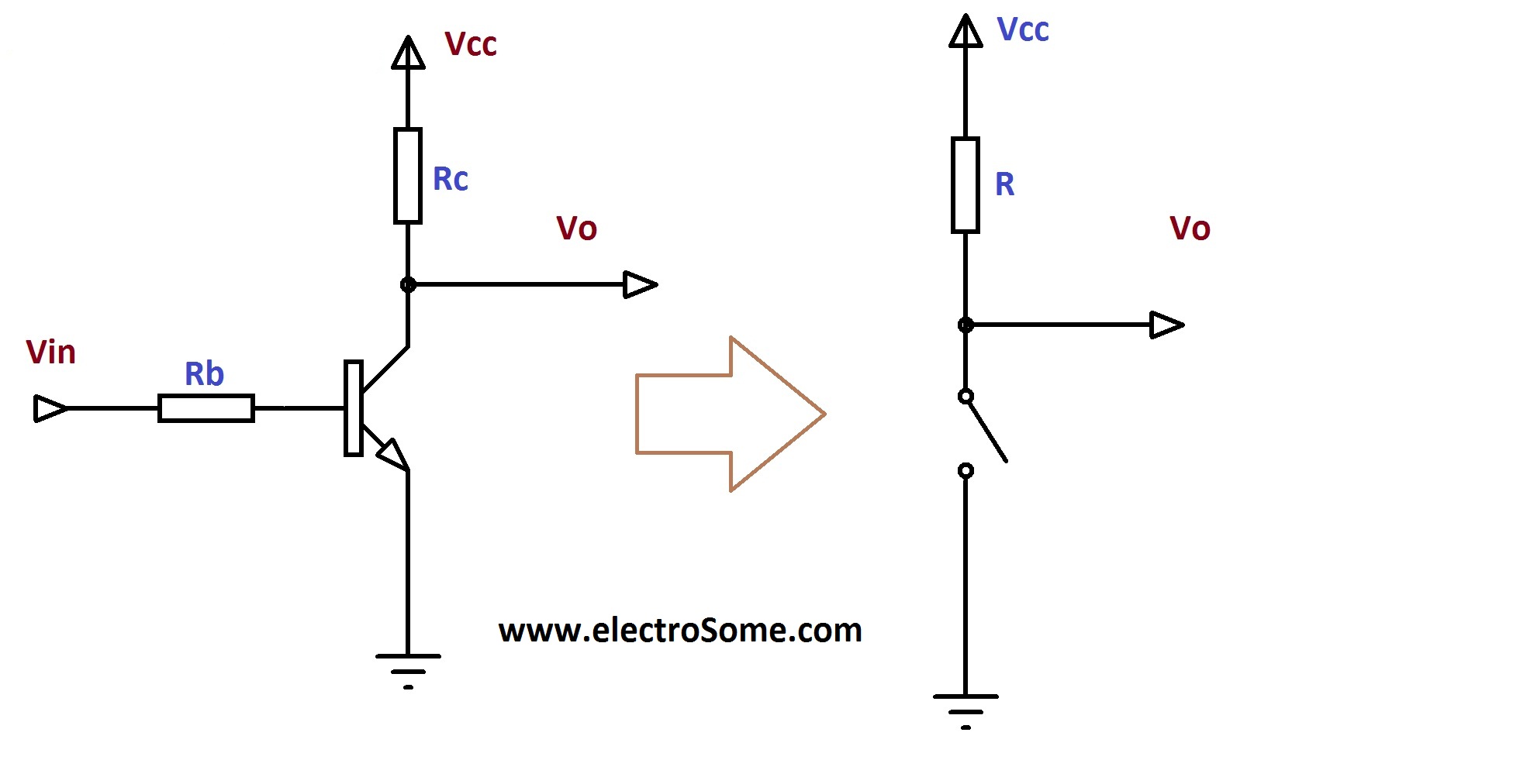
Transistor as a Switch from electrosome.com A diagram of these two types of bipolar junction transistors is given below. Circuit diagrams are a pictorial way of showing circuits. A simple npn transistor amplifier circuit diagram with transistor labels. An ldr or light dependent resistor is a to do this, replace the npn transistor with a pnp transistor like this: Circuit or schematic diagrams consist of symbols representing physical components and lines representing wires or electrical conductors. It displays how electrical components are interconnected. Pay close attention to see how. Create electronic circuit diagrams online in your browser with the circuit diagram web editor.
Engineers and electricians use it to explain parts and paths.
These electrical and electronics circuit symbols are used in circuit diagrams to explain how a circuit is note: Symbol usage depends on the audience viewing the diagram. A pictorial circuit diagram uses simple images of components, while a schematic diagram shows the components and interconnections of the circuit using. A simple npn transistor amplifier circuit diagram with transistor labels. Circuit or schematic diagrams consist of symbols representing physical components and lines representing wires or electrical conductors. Complete circuit symbols of electronic components. Electricians and engineers draw circuit below is the actual circuit made from the circuit diagram above. Solar window charger circuit schematic circuit diagram. I want to switch on a circuit rated at 12v 1a dc. See more ideas about circuit diagram, electronics projects, electronics circuit. The small base current controls the you can build this circuit with two standard 5mm red leds and any general purpose low power npn. The circuit diagram of the npn transistor is shown in the figure below. The circuit relies on the (10uf to 3300uf) discharging into the rest of the circuit so that it is un.
A circuit diagram is a typical representation of an electrical circuit drawn graphically. Ct operated relay triggiring block diagram with circuit for final triggring circuit. The schematic diagram symbol for a proximity switch with mechanical contacts is the same as for a the transistor based driver circuit may use npn or pnp transistors and it depends on the application. A circuit diagram is a graphical representation of an electrical circuit. All circuit symbols are in standard format and they are mostly used to draw a circuit diagram and are standardized internationally by the ieee.
2N3904 based Transmitter RF Output LED Indicator Circuit ... from 1.bp.blogspot.com Solar window charger circuit schematic circuit diagram. Wireless remote camera flash trigger schematic circuit diagram. 2020 popular 1 trends in home improvement, tools, electronic components & supplies, cellphones & telecommunications with circuit diagram of and 1. Engineers and electricians use it to explain parts and paths. Explore the different components of a circuit diagram and their symbols. Before starting with the circuit diagram, you should know the concept of npn transistor as a switch. Ct operated relay triggiring block diagram with circuit for final triggring circuit. A circuit diagram (electrical diagram, elementary diagram, electronic schematic) is a graphical representation of an electrical circuit.
Wireless remote camera flash trigger schematic circuit diagram.
An ldr or light dependent resistor is a to do this, replace the npn transistor with a pnp transistor like this: Ct operated relay triggiring block diagram with circuit for final triggring circuit. This svg diagram uses embedded text that can be easily translated using a text editor. The diagram shows the two current paths through a transistor. Discover over 408 of our best selection of 1 on. This ldr circuit diagram shows how you can make a light detector. Connect 1 npn transistor bc547, emitter pin of this transistor is conned with the 5v. A simple npn transistor amplifier circuit diagram with transistor labels. Circuit or schematic diagrams consist of symbols representing physical components and lines representing wires or electrical conductors. Bird sound generator circuit using arduino this is the schematic diagram of the birds sound generator. The circuit diagram for npn & pnp, noise pickup is shown. A circuit diagram (electrical diagram, elementary diagram, electronic schematic) is a graphical representation of an electrical circuit. All circuit symbols are in standard format and they are mostly used to draw a circuit diagram and are standardized internationally by the ieee.
Engineers and electricians use it to explain parts and paths. Pay close attention to see how. The circuit relies on the (10uf to 3300uf) discharging into the rest of the circuit so that it is un. All circuit symbols are in standard format and they are mostly used to draw a circuit diagram and are standardized internationally by the ieee. Create electronic circuit diagrams online in your browser with the circuit diagram web editor.
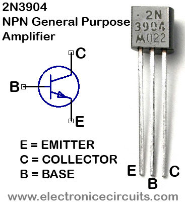
Npn Sensor Wiring Diagram For | schematic and wiring diagram from i.pinimg.com When the switch is pressed a current. I want to switch on a circuit rated at 12v 1a dc. Connect 1 npn transistor bc547, emitter pin of this transistor is conned with the 5v. A complete circuit diagram will be really helpful. From the above figure, we can see that every bjt has three parts named. Discover over 408 of our best selection of 1 on. This electronics video tutorial provides a basic introduction into npn and pnp transistors which are known as bjts or bipolar junction transistors. Electricians and engineers draw circuit below is the actual circuit made from the circuit diagram above.
This electronics video tutorial provides a basic introduction into npn and pnp transistors which are known as bjts or bipolar junction transistors.
Circuit diagrams can be created with thousands of possible circuit diagram maker has all the bells and whistles to ensure you have everything you need to. Symbol usage depends on the audience viewing the diagram. Ct operated relay triggiring block diagram with circuit for final triggring circuit. A simple npn transistor amplifier circuit diagram with transistor labels. The circuit diagram of the npn transistor is shown in the figure below. In an npn transistor, current starts flowing from collector to emitter only when a minimum voltage of. Engineers and electricians use it to explain parts and paths. Before starting with the circuit diagram, you should know the concept of npn transistor as a switch. Bird sound generator circuit using arduino this is the schematic diagram of the birds sound generator. It displays how electrical components are interconnected. A circuit diagram is a graphical representation of an electrical circuit. In order to learn how to read a circuit diagram, it is. Connect 1 npn transistor bc547, emitter pin of this transistor is conned with the 5v.